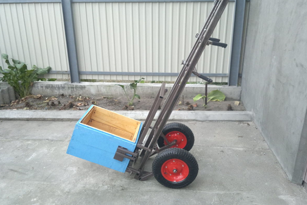
Large apiaries require a special lift—an apilift—to transport bee compartments. This is a metal structure with a gripping section and wheels for movement. You can assemble it yourself using ready-made plans and step-by-step instructions.
Design and operating principle
The main parts of the hive lift are:
- FramesThe first frame is stationary, acting as the structure's skeleton, while the second moves parallel to the first, providing reliable support for the load. The frames are made of square-section metal tubing. The thickness of the tubing determines the load capacity and wear resistance of the finished trolley.
- CarriageIt bears the weight of the hive, so the load on it is enormous. The carriage's final cross stops are used to secure the side clamps, holding the hive in place. The central stop is used to secure the torso—the winch element that lifts and lowers the load.
- ForksThese are sturdy angles that fit into the carriage and serve as the hive's lifting element. The load is placed on them.
- BearingsThe design features six bearings, four of which are on the bracket and two on the wheels. These ensure the cart is easy to control and moves smoothly.
- LeverAllows you to lift the hive to a significant height from the ground. The cart is moved to the load, the width is adjusted using a screw and bracket, and then the hive is lifted off the ground with a lever and transported to the desired location.
- Wheels with bracketThis component of the cart is a single piece and acts as a welded guide, but can be removed for disassembly and transport. The bracket is attached to the frame by tightening two through bolts at the bottom and top of the structure, and is then secured with a wing nut, helping to securely hold the hive. Wheels with bearings are needed to move the entire apilift. They should be wide, have a strong, solid base, inflatable chambers, and a grooved tire for easy slippage.
The apilift differs from a simple cart precisely by the presence of clamps and a system of levers for pushing up.
The operating principle of such a device is simple:
- The side clamps of the structure securely hold the hive in place.
- The lever handle lifts the load from the ground level to a certain height.
- The lift on wheels rolls to the desired location.
- The load is lowered to the ground also using a lever handle.
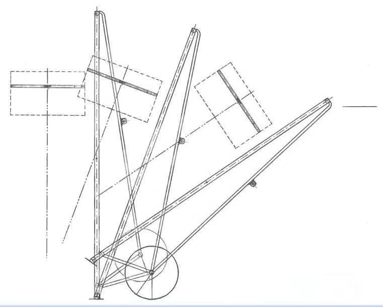
A design with this operating principle looks like this:
Lift requirements and standard drawings
A mobile unit is used to transport heavy and large hives, so it must ensure the cargo's safety throughout the journey. To ensure this, a homemade apilift must have the following characteristics:
- Load capacity up to 120-130 kgOn average, one compartment weighs 40-42 kg, so the cart can transport either a triple hive or three separate parts.
- The working width is approximately 35-55 cmHives can vary in size, so it's a good idea to provide adjustable side clamps to grip and adjust the width depending on the load's dimensions.
Correct placement of the clamps will allow you to secure a heavy load without applying much physical effort.
- Lifting height up to 130 cmThe installation should raise the hive to a height of up to 130 cm so that it does not drag along the ground during movement.
- Descent accuracy of 1 cmWhen properly manufactured, the load can be moved with an accuracy of 1 cm, significantly reducing the beekeeper's workload by eliminating the need to lift and move the load. Furthermore, the apilift itself won't feel the weight of the hive, as the pressure on the handle is only 1 kg.
The lifting mechanism for the apilift can be manual or mechanical, but to make the work easier, most beekeepers make the cart themselves with an automatic drive.
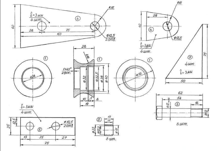
Once you've determined the parameters of your future lifting device, you need to prepare a drawing. Here's a sample drawing of a standard trolley with a lifting capacity of up to 130 kg:
Step-by-step assembly instructions
To assemble the lift you will need the following materials and tools:
- square section profile pipes – 40x20, 30x20, 25x25 mm;
- bolts (M6, M8) and nuts;
- handle with non-slip coating (rubberized or any other);
- strong tension springs;
- steel cable with a diameter of 3-4 mm;
- a reel with the following parameters: height – 34 mm, outer diameter – 50 mm, inner diameter – 30 mm;
- handle for the reel for winding the cable;
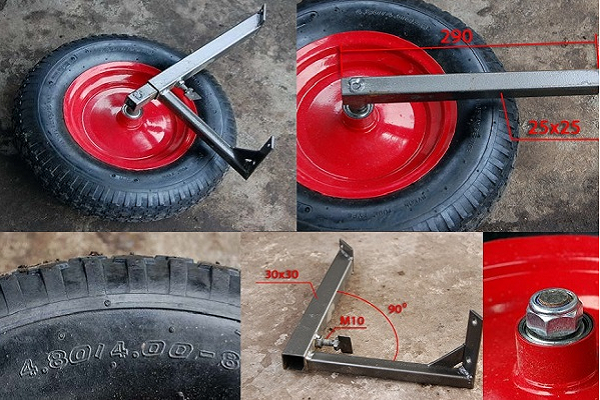
- wheels with an outer diameter of 380-400 mm – 2 pieces;
- rollers with bearings;
- welding machine;
- Bulgarian;
- Measuring tape.
- ✓ Use anti-corrosion coating on all metal parts of the lift to increase its service life.
- ✓ Check all bolts for tightness before first use. Loose bolts may cause instability.
Once you've gathered everything you need, you can begin assembling the cart. This process can be roughly divided into three stages, each requiring separate consideration.
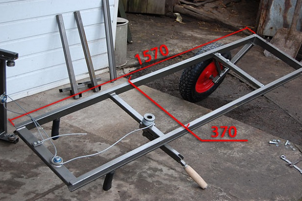
Step 1: Assembling the frame
The basis of the entire structure is the frame, which must be made as follows:
- Weld the frame from the side posts so that when finished its length is 1570 mm and the width is 370 mm.

- Weld four pipes perpendicularly to the finished frame. Attach the outer beam flat to the side members. The top and bottom crossbars should match the dimensions of the frame pipes (40x20 mm). For the middle crossbars, use smaller pipes (30x20 mm). Install the second beam 500 mm from the top crossbar, and the third 380-400 mm from the bottom.
- Make a 200 mm vertical cut along the outside of the frame pillars specifically for the bearing. Install M6 bolts along the edges of the cut, otherwise the bearing will fall out of the groove during operation of the bogie.
- On both sides of the third beam, going from above, drill one hole for M bolts. Wheel brackets will be installed in these places later.
- Step back 200-300 mm from the top beam and weld rubberized handles to the side pipes.


Step 2: Installing the reel, lift mechanism and wheels
At this stage, the assembled frame is equipped with all the necessary components to enable future cargo transportation. They are assembled in the following order:
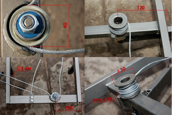
- Install a 40 mm diameter bearing on the upper crossbar, keeping it 130 mm from the right edge of the frame. Attach a retainer (fastener) on top of the bearing to prevent the cable from falling out of the block lifting the load.
- On the left side of the frame, also at a distance of 130 mm from the first crossbar, install a roller groove and insert a steel cable into it, the upper free end of which is bolted to the left side.
- Mount the spool on the second crossbar from the top, facing the frame, keeping a 120 mm gap from the right edge. Install the spool axle in the bearing, which will be used to wind the cable when lifting heavy objects.
- On the opposite side of the reel, also on the second beam, weld a 200 mm lever. It should have a handle that rotates freely around its axis.
- Nail a piece of steel rod near the reel and lever, which will act as metal stoppers.
- Using a cable, connect the lever handle to the metal tongue and spring. The tongue will help prevent the loaded carriage from accidentally descending. When at rest, it will be pressed against the stop by the spring. At this point, the lifting mechanism looks like this:

- Make brackets from 25x25 mm profile tubing to mount the wheel axles. Secure them with nuts for external mounting.
- Attach the brackets to the frame using rectangular steel plates measuring 110 x 25 mm. Visually, the brackets should be two pipes measuring 300 and 230 mm, welded perpendicularly and connected to the frame using through bolts M

A structure constructed using this design can easily tilt toward the ground at various angles. This is achieved by wheels extending from brackets.
Step 3: Installing the carriage, fork, and clamps
The final, but no less important, step in creating an apilift involves the following steps:
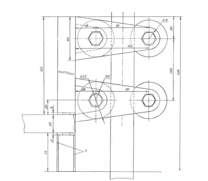
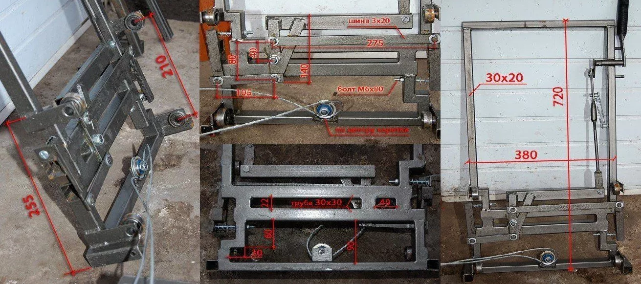
- Assemble the carriage—a lifting device consisting of numerous parts, including clamps for securing the load. To do this, first create a frame with bearings measuring 720 x 380 mm. Use 30 x 20 mm pipe for the frame. At the bottom, create two crossbars from 30 x 30 mm pipe. These will house the side clamps that grip the hive body.
The hinge tilts under the applied thrust, and the square that pulls the tube from the side clamp becomes skewed. The hinge's tilt angle is adjusted using a spring-loaded bolt, which affects the clamp's adjustment. The greater the tilt, the more intense the compression.
- Make clamps from 25x25 mm diameter pipes 450 mm long. Weld "legs" perpendicular to the ends of these pipes to hold the load—90 or 130 mm long pieces. To prevent the hive body from slipping, it's advisable to make the inward-facing portion of the "legs" ribbed. Insert the prepared clamps into the larger diameter pipes on the carriage.
- Weld a cable block to the center of the carriage's lower crossbar. The vertical movement of the structure will be achieved by four bearings located on the sides of the axle frame.
- To lift the load from the bottom, attach 25x25 mm diameter, 90 mm long tubes to the sides of the carriage bottom. Use M-bolts for this. To create the forks, attach 450-500 mm long tubes to the installed sections. The carriage compression mechanism will be achieved using a lever with a rod.
Video tutorial
The video below explains the key considerations when building an apilift:
Helpful tips
When using a homemade apiary cart, it is worth considering a number of rules:
- Before using the lift for full operation, check its technical condition. To do this, first operate it without a load, paying particular attention to the following:
- fixing screws and nuts, especially in those areas where the cable rollers are secured;
- tightness of the fit of the support frame bolts fixed with washers;
- the completeness of the fasteners' entry into the grooves.
- If hives with heavy honeycombs are being transported, check that they are securely fastened.
- If possible, remove all unnecessary components from the hive. In particular, remove any moving parts that might frighten the bees.
- Check the tightness of the frame fastenings inside the box. If the honeycomb breaks during transportation, this will provoke aggression from the insects. Furthermore, some of them may die.
- When loading the hive, make sure the handle lock is secure, as it may pop out when the cart tilts, causing the load to fall.
- When transporting bees, wear protective clothing and carry a spray bottle and net. These measures will help protect you from insect stings in the event of an accident.
With some effort, you can assemble the apilift yourself, saving you significant money compared to purchasing a commercial apiary cart. However, careful attention must be paid to the installation of small components, which will determine the technical characteristics of the finished mobile unit.